




“Liquid cooling” is often treated like it describes one kind of data center system. In practice, the phrase covers architectures with very different fluid paths, fluids, connection points, and material requirements.
In one system, coolant may stay inside cold plates, manifolds, and quick-disconnect fittings. In another, the liquid may remain outside the server and cool the exhaust air at the rack boundary. In immersion systems, the fluid may contact every server material inside the tank. In two-phase systems, seals and fittings may also need to account for vapor, condensate, and fluid loss.
Those differences matter before any tubing, hose assembly, fitting, gasket, seal, or quick-disconnect is specified. The architecture determines the fluid path, the connection points, the fluid type, and the material requirements. A component well-suited to a water-based cold plate loop may be entirely wrong for a dielectric immersion tank. A seal used in a rack-level quick-disconnect may face a very different duty cycle than a gasket used on an immersion tank lid.
This article maps five liquid cooling architectures from a fluid handling standpoint:
- 1. Single-phase direct-to-chip cooling
- 2. Two-phase direct-to-chip cooling
- 3. Rear-door heat exchangers
- 4. Single-phase immersion cooling
- 5. Two-phase immersion cooling
These architectures are not steps on a maturity ladder. Rear-door heat exchangers are not an early version of immersion, and two-phase direct-to-chip cooling is not the same thing as two-phase immersion. Each architecture has a different fluid path, a different service model, and a different set of tradeoffs for the components responsible for moving and containing the fluid.
Why the Architecture Matters Before Anything Else
When a procurement team or systems engineer is selecting flexible hose, quick-disconnect fittings, seals, tank gaskets, or other fluid handling components for a liquid cooling project, the first question is not the temperature rating or the working pressure. It is which architecture the system uses.
The architecture determines where the fluid goes and what it touches. That determines the fluid chemistry, the connection type, the mechanical environment, and the material family that is appropriate. A component that works in one liquid cooling architecture may be entirely wrong for another, even when both systems are described with the same general term.
This is especially important because liquid cooling is no longer defined only by whether fluid is present. It is also defined by where that fluid is located and whether it remains liquid throughout the loop. Single-phase direct-to-chip cooling and two-phase direct-to-chip cooling both bring fluid to the chip package, but they create different sealing, compatibility, and service requirements. Single-phase immersion and two-phase immersion both place servers in dielectric fluid, but two-phase immersion adds vapor containment and pressure management to the design challenge.
For fluid handling components, the architecture is the starting map. It tells the engineer whether the main concern is repeated connection cycles, hose routing in a live rack, door movement, tank sealing, cable penetrations, vapor containment, or compatibility with a specific dielectric fluid.
Where the Liquid Lives in Each Architecture
The simplest way to compare the five architectures from a fluid handling standpoint is to ask where the liquid actually is, what it comes into direct contact with, and what that means for the components responsible for moving and containing it.
| Architecture | Where the liquid is | What it contacts directly | What that determines for fluid handling |
| Single-phase direct-to-chip | CDU, rack manifolds, hose drops, quick-disconnects, and cold plates. The coolant remains liquid throughout the server-side loop. | Cold plate channels, hose bores, manifold fittings, quick-disconnect seals, CDU internal components | Compact hose routing, serviceable connections, coolant formulation compatibility, bend radius, pressure drop, and leak prevention in live rack environments
|
| Two-phase direct-to-chip | Evaporator-style cold plates and a closed server-side loop that may contain liquid, vapor, or a vapor-liquid mixture. | Cold plate channels, vapor-liquid return paths, condenser or CDU interfaces, fittings, seals, and service ports | Dielectric or engineered fluid compatibility, phase change behavior, pressure control, fluid charge management, and liquid/vapor sealing
|
| Rear-door heat exchanger | Door-mounted heat exchanger coil and external facility or rack piping. The servers remain air-cooled internally. | Heat exchanger coil passages, door inlet and outlet connections, hose assemblies, flow balancing valves | Connections must accommodate door movement, continuous fan vibration, service access, and water-based fluid compatibility
|
| Single-phase immersion | The entire tank environment. Servers and supporting materials are submerged in dielectric liquid that remains liquid during operation. | Server boards, cables, connectors, labels, adhesives, coatings, tank lid seals, penetration seals, external circulation loop components | Fluid handling scope expands beyond hose and fittings. Every wetted material requires compatibility review against the specific dielectric fluid
|
| Two-phase immersion | Liquid and vapor phases inside a sealed tank. The secondary condenser water circuit is separate. | Submerged server materials, vapor-side tank seals, condenser circuit penetrations, cable and instrument seals, condensate return surfaces | Sealed containment design, low-surface-tension fluid behavior, vapor-side exposure, pressure management, and fluid loss control
|
Architecture 1: Single-Phase Direct-to-Chip Cooling
The Mainstream Architecture for High-Density AI and HPC Rack Deployments
What It Does
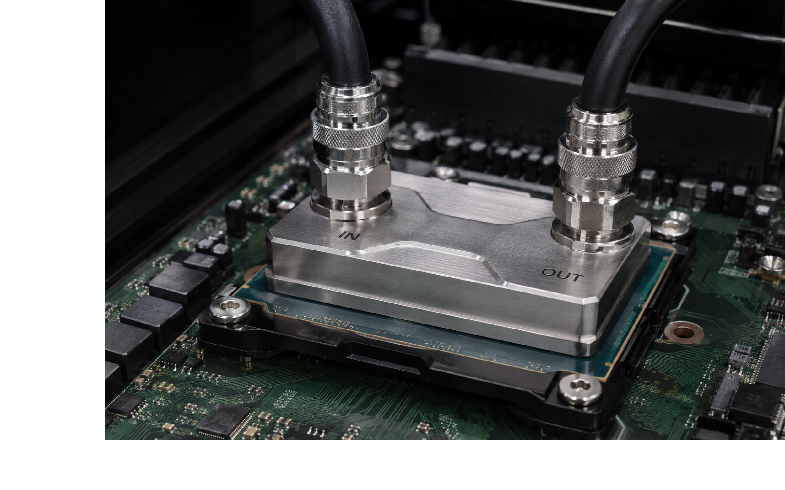 Single-phase direct-to-chip cooling places a metal cold plate directly on high-power components such as CPUs, GPUs, accelerators, memory modules, networking ASICs, or other heat-generating devices. Coolant flows through channels inside the cold plate, absorbs heat at the component, and returns to a cooling distribution unit, or CDU, where the heat is transferred to another loop.
The term single-phase means the coolant remains liquid throughout the server-side loop. It warms as it absorbs heat, but it does not intentionally boil inside the cold plate. The rest of the rack may still be air-cooled by server fans, which handle heat from components that are not connected directly to cold plates.
This has become the primary liquid cooling path for many high-density AI and HPC deployments because it targets the highest-power components without requiring the full server environment to be submerged. It also fits into a growing ecosystem of CDUs, rack manifolds, quick-disconnect fittings, blind-mate interfaces, leak detection systems, and integration practices.
Single-phase direct-to-chip cooling has also scaled significantly over the last few years. Older assumptions that treated D2C as a moderate-density bridge between air cooling and immersion are becoming less useful. Modern cold plates, rack manifolds, CDUs, and server designs have narrowed the density gap between D2C and immersion, and that trend is expected to continue as rack-level integration improves.
How the Fluid Path Works
Coolant leaves the CDU, travels through a rack-level supply manifold, and reaches each server through a flexible hose assembly, tube assembly, quick-disconnect, or blind-mate interface. Inside the server, it flows through cold plates mounted on the highest-power components, absorbs heat, and returns through a parallel return manifold back to the CDU.
At the CDU, a heat exchanger transfers the accumulated heat to a facility-side loop or other heat rejection system. The server-side loop and the facility-side loop are separate, and the boundary between them is one of the most important parts of the system architecture. The server-side loop may have different chemistry, materials, maintenance requirements, and ownership than the facility water system.
The Technology Cooling System, or TCS, refers to the server-side cooling loop between the CDU and the cold plates or other liquid-cooled components in the rack. In single-phase D2C systems, that loop may use a treated water-based heat transfer fluid or a glycol/water heat transfer fluid, depending on the system design, facility requirements, freeze protection needs, operating temperature, materials of construction, water treatment strategy, and maintenance model.
This distinction is becoming more important as high-density AI and HPC deployments mature. Water-based fluids can offer thermal advantages because water has strong heat transfer properties, including high specific heat and thermal conductivity. Adding glycol can reduce freeze risk and support certain operational strategies, but it also changes the thermal properties of the coolant, including specific heat, thermal conductivity, viscosity, and pump power requirements. The right choice is not simply “water versus glycol.” It is a system-level decision that has to account for thermal performance, reliability, serviceability, corrosion control, biological control, facility conditions, and the full wetted-materials list.
The Open Compute Project has published separate guidance for water-based and propylene glycol-based heat transfer fluids used in single-phase cold plate-based liquid-cooled racks. That split is useful because it reflects where the market is heading: water-based and glycol/water approaches both have legitimate roles, but they should not be treated as interchangeable. Each fluid strategy brings its own requirements for inhibitors, filtration, monitoring, compatibility, flushing, commissioning, and long-term maintenance.
For tubing, fittings, and seals, the important point is not whether the coolant can be summarized as water, glycol/water, or propylene glycol. It is the complete formulation. Water quality, inhibitor chemistry, additive package, operating temperature, metals in the loop, elastomer selection, microbial control strategy, and maintenance practices all influence compatibility.
Where Tubing, Fittings, and Seals Appear
CDU-to-rack manifold connections bridge the fixed cooling infrastructure to the rack-level distribution system. These connections run in constrained spaces behind or near the rack and must be routed within the minimum bend radius of the hose or tube assembly.
Rack manifolds distribute coolant to multiple servers or trays. They define the supply and return paths, create the service interface, and help determine pressure drop, flow balance, isolation strategy, and upgrade flexibility.
Manifold-to-server hose drops connect each server’s cold plate inlet and outlet to the rack supply and return manifolds. These assemblies are usually short, but the routing space is tight. Hose flexibility, bend radius, and strain relief are practical design constraints rather than secondary details.
Quick-disconnect fittings are the key service points in many D2C systems. They allow servers to be installed or removed without draining the loop. Dripless or dry-break designs help prevent coolant from reaching server hardware during service events.
Blind-mate manifold interfaces are used in some rack designs to engage automatically when a server sled is inserted. These interfaces require precise alignment, tolerance for minor misalignment, contamination resistance, and reliable sealing over repeated service cycles.
CDU internal connections include pump connections, heat exchanger ports, bypass circuits, pressure relief lines, sensors, vents, drains, and sampling ports. These are lower-activity connections than server interfaces, but they are still exposed to the full temperature, pressure, and chemistry of the server-side loop.
What Matters for Fluid Handling in Single-Phase D2C
The defining challenge in single-phase direct-to-chip cooling is serviceable liquid inside a live rack environment. Every server swap can involve actuating fluid connections, so quick-disconnect seal condition, cycle life, actuation force, dripless performance, and misalignment tolerance become practical selection criteria.
Hose routing is just as important. Rear-of-rack space is crowded, and routing tension can load fitting interfaces over time. Strain relief at fitting ends helps prevent hose weight, bend stress, and service movement from becoming long-term reliability issues.
Compatibility review should be based on the actual coolant formulation, not a broad description such as water, treated water, glycol/water, or propylene glycol. A water-based TCS loop still requires control of corrosion, conductivity, particulates, biological activity, and material compatibility. A glycol/water loop adds its own considerations around concentration, viscosity, inhibitor chemistry, thermal performance, and long-term fluid monitoring. In both cases, the fluid and the wetted-materials list should be evaluated together rather than treated as separate decisions.
Architecture 2: Two-Phase Direct-to-Chip Cooling
Phase Change at the Cold Plate, Not in an Immersion Tank
What It Does
Two-phase direct-to-chip cooling also brings fluid directly to high-power components, but the heat transfer mechanism is different. Instead of keeping the coolant liquid throughout the cold plate, a two-phase D2C system uses a working fluid that changes phase as it absorbs heat from the chip package.
That distinction matters because two-phase cooling is often associated with immersion. Two-phase D2C is different. The server is not submerged in a boiling bath. Phase change occurs inside an engineered cold plate, evaporator, or closed loop connected to the heat-generating component.
The appeal is the latent heat of phase change. A fluid can absorb a large amount of heat during boiling or evaporation while maintaining a relatively controlled temperature. That makes two-phase D2C attractive for high heat flux applications where single-phase cold plates may face limits related to flow distribution, pressure drop, or temperature uniformity.
Two-phase D2C is more specialized than single-phase D2C, and the ecosystem is less mature. It deserves its own category, however, because the fluid handling implications are different from both single-phase direct-to-chip cooling and two-phase immersion cooling.
How the Fluid Path Works
In a two-phase D2C system, liquid working fluid is delivered to an evaporator-style cold plate or heat exchanger mounted on the high-power component. As the fluid absorbs heat, some portion changes phase from liquid to vapor. The vapor or vapor-liquid mixture then returns to a condenser, CDU, or heat rejection unit, where it condenses back into liquid and recirculates.
Different system designs may manage this loop in different ways. Some may use pumped two-phase circulation, while others may rely more heavily on pressure-driven flow, vapor-liquid separation, or thermosyphon behavior. The common feature is that the cooling loop must manage both liquid and vapor behavior.
The working fluid may be a dielectric fluid, refrigerant, or other engineered heat transfer fluid selected for phase-change performance. That fluid is not simply a carrier of heat. It is part of the thermodynamic design, which means its boiling point, pressure behavior, material compatibility, surface tension, volatility, and stability all matter.
Where Tubing, Fittings, and Seals Appear
The evaporator cold plate is the central fluid handling component in the system. It must distribute liquid across high heat flux regions, support controlled boiling or evaporation, and return vapor or vapor-liquid mixture without dryout, excessive pressure drop, or maldistribution.
Supply and return connections may see different physical states of the working fluid. The supply side may be mostly liquid, while the return side may contain vapor, liquid, or a two-phase mixture depending on the operating condition. This affects line sizing, pressure drop, routing, seal exposure, and service behavior.
Condenser or CDU connections transfer heat from the two-phase loop to a secondary cooling path. These interfaces may look similar to other liquid cooling systems from the outside, but the internal working fluid can create different compatibility and sealing requirements.
Fill, drain, vent, charge, and service ports are especially important. A two-phase system depends on the correct fluid inventory and purity. Small leaks, air ingress, contamination, or changes in charge volume can affect thermal performance.
Quick-disconnect or blind-mate interfaces may be possible in serviceable rack designs, but they are more challenging than in single-phase water-based systems. They must account not only for leakage prevention, but also for fluid charge, vapor release, contamination control, and reliable reconnection.
What Matters for Fluid Handling in Two-Phase D2C
Two-phase D2C should not be treated as single-phase D2C with a different coolant. Phase change changes the pressure environment, sealing requirements, service procedures, and qualification burden.
Materials should be evaluated against the actual working fluid under realistic exposure conditions. A room-temperature liquid soak may not capture vapor exposure, thermal cycling, pressure cycling, or the behavior of low-surface-tension fluids at sealing interfaces.
Serviceability is also more complex. Preventing drips remains important, but the system may also need to preserve fluid charge, prevent vapor loss, avoid air ingress, and maintain fluid purity. For fluid handling components, that means fittings, seals, and service ports become part of the thermal control strategy.
Architecture 3: Rear-Door Heat Exchangers
The Most Retrofit-Friendly Option: Liquid Cooling at the Rack Boundary Without Touching the Servers
What It Does
A rear-door heat exchanger replaces the standard rear door of a server rack with a door-mounted liquid-cooled heat exchanger. Chilled water or another water-based cooling fluid circulates through the coil, and server fans push hot exhaust air through it as air exits the rack. Heat transfers from the exhaust air to the cooling fluid before the air enters the hot aisle or exhaust plenum.
No modification to the servers is required. Standard servers operate in standard racks, and the changes are limited to the rack door, hose connections, and facility cooling infrastructure. This is what makes RDHx the most retrofit-friendly of the five architectures.
RDHx does not eliminate air cooling. The servers still rely on their internal fans to move air across components inside the chassis. The heat exchanger captures heat from that airflow before it becomes a room cooling problem.
The capability of RDHx has moved upward as active rear-door designs, improved coils, and more optimized deployments have developed. Older assumptions that limited rear-door heat exchangers to relatively modest rack densities are increasingly dated. The practical limitation is not that liquid cannot remove the heat. It is that RDHx still depends on server airflow, fan power, coil approach temperature, and airside heat transfer through the door.
How the Fluid Path Works
Cooling fluid enters the heat exchanger coil through the door inlet connection, circulates through the coil across the door surface, absorbs heat from the server exhaust air, and exits through the outlet. The loop connects back to the facility chilled water plant, a row-level cooling unit, or another heat rejection system.
In multi-rack deployments, flow balancing valves distribute flow across racks and allow the cooling load to be equalized between rows. The system may be designed to reduce exhaust air temperature enough that the air leaving the rack is close to room-neutral.
The fluid path is external to the server environment throughout. Heat moves from server components into air, from air into the rear-door coil, and from the coil into the cooling fluid. That airside step is what defines both the benefit and the limitation of RDHx.
Where Tubing, Fittings, and Seals Appear
Door inlet and outlet connections are the primary flexible connections where the facility piping meets the door-mounted heat exchanger. They must allow the door to open and close freely without stressing the fitting interfaces.
Hinge-side hose routing is a major specification point. The hose needs enough flexibility and slack to move with the door, but not so much that it interferes with service access, cable management, or airflow. Bend radius, strain relief, fitting orientation, and support points matter.
Rack-to-facility piping connections connect the rack-level loop to the row or facility-level distribution system. These flexible assemblies can accommodate minor positional variation in rack placement and installation tolerances.
Flow balancing valve connections support multi-rack flow management. Short flexible sections may be used around balancing valves, isolation valves, or other control points.
Drain and vent connections support commissioning and maintenance. These are often small and low-flow, but reliable sealing matters because chronic low-level leakage can become a recurring maintenance issue.
Coil manifold fittings inside the door connect the coil to the inlet and outlet ports. These are usually static connections, but they see temperature cycling and continuous vibration from server airflow and fan operation.
What Matters for Fluid Handling in RDHx
The door inlet and outlet connections are the components in an RDHx system that require the most specification attention. They must be flexible enough to allow door movement, robust enough to tolerate repeated service access, and routed carefully enough to avoid long-term stress at the fitting interface.
Fluid compatibility is usually more straightforward than in immersion architectures because many RDHx systems use water-based cooling fluids. That does not mean compatibility can be ignored, especially when additives or inhibitors are present, but the fluid chemistry is generally less exotic than dielectric immersion fluids.
The larger issue is mechanical. RDHx connections must tolerate door movement, fan-induced vibration, installation variation, and service access. The hose assembly is not just a fluid conduit. It is a moving connection at the rack boundary.
Architecture 4: Single-Phase Immersion Cooling
The Entire Server Environment Becomes a Fluid Handling Problem
What It Does
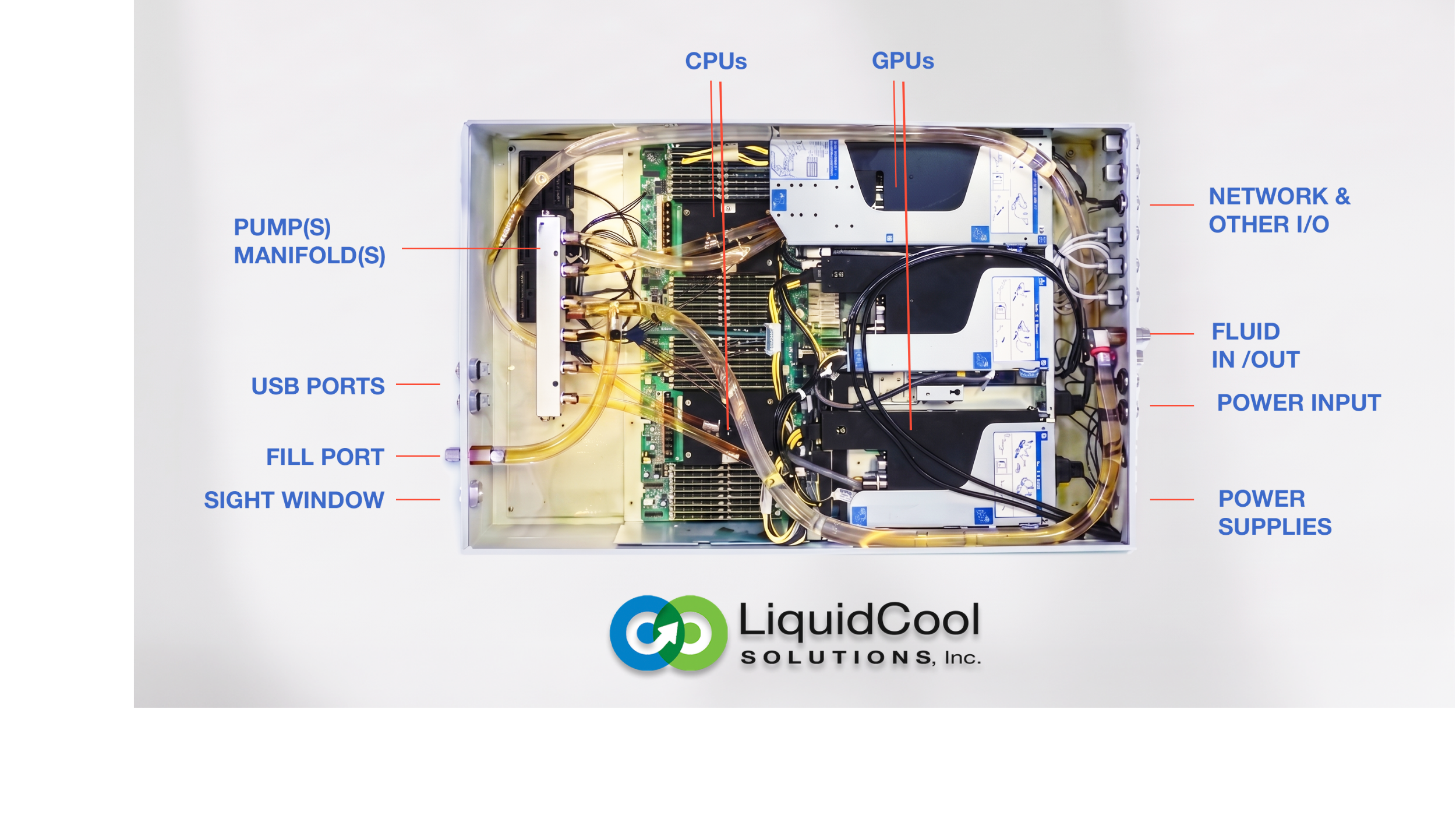
In single-phase immersion cooling, servers are submerged in a non-conductive dielectric liquid. The liquid absorbs heat directly from server components without relying on conventional server airflow. Heated dielectric fluid moves through the tank by convection, forced circulation, or a combination of both, then transfers heat to a heat exchanger.
The term single-phase means the dielectric fluid remains liquid throughout operation. It does not intentionally boil at the server components, which distinguishes it from two-phase immersion.
Immersion requires a more significant operational change than D2C or RDHx. Servers must be qualified for immersion, which means reviewing not only the main board and components, but also cables, connectors, labels, adhesives, conformal coatings, drive seals, elastomers, plastics, and any other materials that will remain submerged. Fans are typically removed, and the server enclosure or service procedure may need modification.
Single-phase immersion can support high-density purpose-built deployments because it removes many of the constraints associated with moving large volumes of air through a server chassis. At the same time, the density gap between immersion and direct-to-chip cooling has narrowed as modern D2C systems have scaled. The more useful distinction is not simply that immersion is higher density. It is that immersion places the complexity in a tank-based operating model, while D2C places more of the complexity in cold plates, manifolds, CDUs, and rack-level service connections.
How the Fluid Path Works
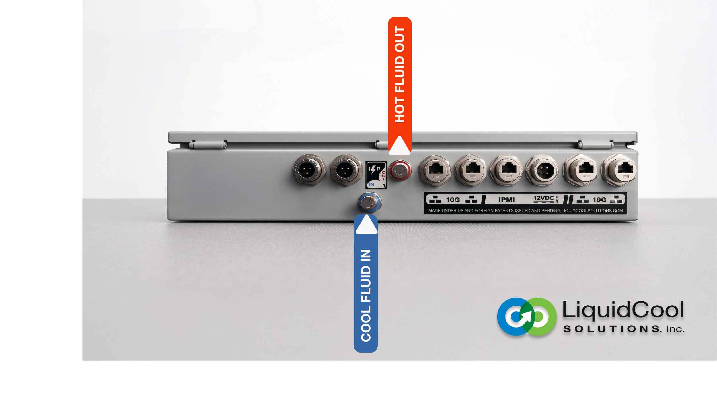
The primary cooling circuit moves heated dielectric fluid from the immersion tank through a pump and external heat exchanger, then returns cooled fluid to the tank. Some systems rely more heavily on natural convection, while others use forced circulation to manage heat transfer and temperature uniformity.
The heat exchanger connects to a secondary facility water circuit, which carries heat to the building cooling plant or other heat rejection system. The dielectric fluid and facility water remain separate.
The tank is the defining feature of the system. It contains the dielectric fluid, the submerged server hardware, and the primary thermal interface between them. The tank design, including fluid volume, circulation pattern, access method, lid design, fill and drain provisions, and sampling strategy, determines how the system is operated and maintained.
Dielectric fluid describes an electrical property, not a single chemical family. Synthetic hydrocarbon fluids, PAO-based fluids, ester-based fluids, and engineered proprietary dielectrics may all be electrically non-conductive, but they can have different chemistries, viscosities, solvency profiles, and material compatibility behavior. Compatibility data for one dielectric fluid should not be assumed to apply to another.
Where Tubing, Fittings, and Seals Appear
Tank inlet and outlet connections are the primary fluid connections where the external circulation circuit meets the tank. These connections must seal against the dielectric fluid under the operating pressure and temperature of the circulation loop.
CDU or heat exchanger-to-tank piping connects the pump, heat exchanger, filter, and tank. Flexible sections may be used to absorb pump vibration, accommodate installation tolerances, and simplify maintenance.
Tank lid seals and gaskets are large-area static seals in continuous contact with dielectric liquid or vapor. They must seal reliably across the operating temperature range, limit evaporative loss where relevant, and support the access requirements of the tank.
Cable and instrument penetrations are critical. Every cable, sensor, monitoring line, or instrument connection that passes through the tank lid or wall is a potential leak path. Each penetration needs a seal compatible with the specific dielectric fluid.
Sampling and monitoring ports support fluid condition monitoring. These are small, low-flow connections, but they must seal reliably over long service intervals because the fluid is expensive and central to system reliability.
Fill, drain, and overflow connections are used during commissioning and maintenance. They may handle large volumes of dielectric fluid, so valve and fitting seals must be compatible with the exact fluid in use.
What Matters for Fluid Handling in Single-Phase Immersion
The most important thing to understand about single-phase immersion is that the fluid handling scope is broader than in D2C or RDHx. The fluid contacts not only hoses and fittings in the external loop, but also every surface inside the tank.
That means compatibility review must include tank lid seals, cable jackets, connector materials, labels, adhesives, coatings, plastics, elastomers, and any other material that will remain in continuous fluid contact. A material that performs well in air, or even in a water-based cooling loop, may swell, soften, extract, embrittle, or shed contaminants in a specific dielectric fluid.
Because dielectric fluids are not one chemical family, there is no universal material recommendation that applies across all immersion deployments. The specific fluid governs the requirements. The fluid selection decision determines the material requirements for every wetted component in the system.
Architecture 5: Two-Phase Immersion Cooling
Thermally Powerful and More Specialized, with Liquid and Vapor as Part of the Design Challenge
What It Does
Two-phase immersion cooling uses the energy of phase change as the primary heat transfer mechanism. Servers are submerged in a dielectric fluid engineered to boil near the operating temperature of the components being cooled. The fluid absorbs heat by boiling, vapor rises through the tank, and a condenser near the tank lid causes the vapor to condense back into liquid.
Phase change allows a large amount of heat to be absorbed at a relatively controlled temperature because latent heat is much larger than the sensible heat absorbed by a temperature rise in liquid. That makes two-phase immersion thermally attractive for very high heat flux applications.
Two-phase immersion is the most specialized of the five architectures. It requires purpose-designed tanks, sealed vapor management infrastructure, compatible fluids, qualified server materials, condenser integration, and a service model built around preserving the sealed environment.
The fluid strategy is especially important. The working fluid is not just a coolant. It is central to the thermal design, environmental profile, maintenance model, and long-term supply strategy of the system.
How the Fluid Path Works
The primary cooling circuit is contained inside the tank. Dielectric fluid boils at hot components, vapor rises to the condenser, and condensed liquid returns to the bath. Facility water or another secondary cooling fluid circulates through the condenser and carries the heat to the building cooling plant.
In passive designs, there may be no pump on the primary dielectric side because vapor naturally rises and condensate returns by gravity. Even in these designs, the system still has to manage pressure, condensation, fluid inventory, thermal transients, and vapor containment.
Because the system includes both liquid and vapor, the tank headspace is part of the fluid handling environment. Materials above the liquid line may be exposed primarily to vapor rather than bulk liquid. That distinction matters because vapor-side exposure can differ from liquid immersion.
Where Tubing, Fittings, and Seals Appear
Tank lid vapor seals are among the most demanding components in a two-phase immersion system. The lid must contain both liquid and vapor phases, limit fluid loss, resist low-surface-tension fluid penetration, and maintain sealing force through thermal cycling and service access.
Condenser water circuit connections connect the internal condenser to the external facility cooling loop. These connections may pass through or near the tank lid and must seal the secondary water side while preserving the vapor boundary of the tank.
Cable and instrument penetrations through the lid are potential vapor loss points. Every penetration is a sealing challenge because low-surface-tension fluids and vapor-phase exposure can find leak paths that may not appear in water-based systems.
Pressure relief connections manage pressure during thermal transients or abnormal conditions. These are vapor-side components and must be compatible with the actual dielectric fluid environment.
Fill, drain, and service connections must control both liquid and vapor loss. Because the fluid inventory is central to system performance, even small losses can matter over time.
Condensate return surfaces include internal tank surfaces and structural elements that guide condensed fluid back to the bath. These materials may see alternating vapor, condensate, and liquid exposure.
What Matters for Fluid Handling in Two-Phase Immersion
Vapor containment is the defining fluid handling challenge in two-phase immersion. The system has to seal against a fluid that may wet surfaces aggressively, enter small gaps, and expose materials to both liquid and vapor over time.
The vapor environment should not be treated as identical to the bulk liquid environment. It may be enriched in more volatile components of the fluid formulation, and vapor-side seals may behave differently than liquid-side seals. Qualification testing should reflect the actual exposure condition.
Low surface tension is another practical consideration. Fluids with low surface tension can wet surfaces and penetrate interfaces more readily than water-based coolants. Sealing interfaces that perform reliably against glycol/water may not perform the same way against a low-surface-tension dielectric fluid.
Two-phase immersion also raises long-term fluid strategy questions. Operators need to consider initial compatibility, long-term sourcing, environmental requirements, handling procedures, fluid recovery, and maintenance practices as part of the system assessment.
Architecture Comparison
The table below summarizes the key characteristics of all five architectures, with a focus on the variables that affect fluid handling component selection.
Single-phase D2C
| Two-phase D2C
| Rear-door HX
| Single-phase immersion
| Two-phase immersion
| |
Heat capture method
| Cold plates on high-power components; coolant remains liquid | Evaporation or boiling inside cold plates or evaporators | Liquid-cooled rack door coil removes heat from server exhaust air | Full server submersion in dielectric liquid | Boiling at hot components; vapor condenses near the tank lid |
Typical fluid type
| Water-based or glycol/water heat transfer fluid with system-specific additives | Dielectric, refrigerant, or engineered phase-change working fluid | Chilled water or water-based facility fluid | Dielectric liquid that remains liquid during operation | Low-boiling dielectric fluid selected for phase-change heat transfer |
Server modification
| Cold plates and liquid-ready server design required | Evaporator-style cold plates and two-phase loop design required | None. Standard servers remain air-cooled internally | Fans typically removed; materials qualified for immersion | Purpose-built or extensively qualified server and tank environment |
Deployment maturity
| Mainstream and scaling quickly for AI and HPC racks | More specialized and less standardized | Established and retrofit-friendly | Commercially deployed, but requires significant process change | Thermally powerful, but the most specialized |
Key fluid handling locations
| CDUs, rack manifolds, hose drops, quick-disconnects, cold plates, vents, drains | Evaporator connections, vapor/liquid return paths, condenser or CDU interfaces, charge and service ports | Door inlet and outlet hoses, hinge-side routing, rack-to-facility connections, balancing valves | Tank inlet and outlet, tank lid seals, cable penetrations, external loop, sampling and drain ports | Tank lid vapor seals, condenser penetrations, cable penetrations, pressure relief, fill and drain connections |
Primary fluid handling consideration
| Coolant formulation compatibility, quick-disconnect performance, hose routing, leak prevention | Phase-change fluid behavior, pressure control, charge management, liquid/vapor sealing | Door movement, fan vibration, hose flexibility, water-based fluid compatibility | Fluid-specific compatibility across every wetted material in the tank | Vapor containment, low-surface-tension sealing, pressure management, and fluid loss control |
What This Means for Tubing, Fittings, and Seals
The Fluid Changes by Architecture
Single-phase D2C and RDHx often use water-based coolants. These may include treated water, glycol/water mixtures, corrosion inhibitors, biocides, antifoams, scale inhibitors, and other additives. The complete formulation matters because additives can influence how polymers and elastomers behave over time.
Immersion and many two-phase systems use dielectric fluids. These fluids are chemically different from water-based coolants, and they are not interchangeable with one another. Synthetic hydrocarbons, PAO-based fluids, ester-based fluids, and engineered phase-change fluids can all behave differently with the same tubing, fitting, seal, gasket, adhesive, or cable material.
For water-based systems, compatibility should be reviewed against the complete coolant formulation. For dielectric systems, compatibility should be reviewed against the exact fluid being used. For two-phase systems, both liquid-side and vapor-side exposure should be considered.
The Connection Type Changes by Architecture
Single-phase D2C systems use frequently serviced rack connections. Quick-disconnects and blind-mate interfaces may be actuated repeatedly as servers are installed, removed, serviced, or upgraded. Seal wear, dripless performance, actuation force, alignment tolerance, and cycle life are central specification concerns.
Two-phase D2C systems may also require serviceable rack connections, but the working fluid adds complexity. The system may need to maintain fluid charge, control vapor release, prevent air ingress, and preserve fluid purity during service.
RDHx systems use flexible connections that move with the rack door. The main challenge is not repeated fluid disconnection, but hose flexing, door motion, vibration, strain relief, and service access.
Single-phase immersion systems use static tank seals and penetration seals in continuous fluid contact. The tank may be accessed infrequently, but the seals and gaskets remain exposed to the dielectric fluid for long periods.
Two-phase immersion systems add vapor-side sealing. The lid, penetrations, pressure relief connections, and condenser interfaces must contain a low-surface-tension dielectric fluid in both liquid and vapor form.
The Service Model Changes by Architecture
The service model determines whether static sealing or dynamic sealing is the more important requirement. In single-phase D2C, servers may be swapped regularly, so dynamic connection performance matters. In RDHx, the system is relatively static after installation, but the door still moves. In immersion, tank access and fluid handling are larger maintenance events. In two-phase immersion, service procedures must preserve vapor containment and fluid inventory.
This means component selection is not only a material compatibility decision. It is a material compatibility decision plus a mechanical design decision plus a service model decision.
The same broad component category can have very different requirements depending on where it sits in the architecture. A quick-disconnect seal, a door hose fitting, a tank lid gasket, and a vapor-side penetration seal may all be described as fluid handling components, but they are not doing the same job.
The Material Family Should Follow the Fluid and Use Case
For water-based coolant systems, the full coolant formulation should be the basis for material compatibility review. For dielectric fluid systems, compatibility should be established against the specific fluid formulation, not a general dielectric category. For two-phase systems, the review should account for liquid exposure, vapor exposure, pressure behavior, and fluid loss mechanisms.
The architecture is the starting point for that review, not the end point. Understanding which architecture a system uses immediately narrows the fluid type, the connection locations, the mechanical environment, and the appropriate material families to consider.
Conclusion
Single-phase direct-to-chip cooling, two-phase direct-to-chip cooling, rear-door heat exchangers, single-phase immersion cooling, and two-phase immersion cooling each use liquid to move heat, but they do it differently, in different parts of the system, with different fluids and different types of connections.
Single-phase D2C concentrates coolant inside cold plates, rack plumbing, manifolds, CDUs, and serviceable server connections. Two-phase D2C brings phase change to the cold plate or server-side loop. RDHx keeps the fluid outside the server environment at the rack boundary. Single-phase immersion expands fluid contact to every surface inside the tank. Two-phase immersion adds vapor management, pressure behavior, and sealed containment to the immersion picture.
Each architecture places tubing, fittings, quick-disconnects, seals, and gaskets in different positions and subjects them to different operating conditions. Selecting the right components starts with knowing which architecture the system uses, understanding where the fluid goes and what it touches, and then working from that map to the material, fitting type, and specification that the actual operating conditions require.
Saint-Gobain ICS supplies tubing, hose assemblies, fittings, and seals for water-based coolant and dielectric fluid environments across data center liquid cooling architectures. For guidance on fluid handling component selection for a specific architecture, fluid type, or service model, the ICS application engineering team is available for technical consultation.

Data center liquid cooling is a thermal management approach that uses liquid to remove heat from servers, racks, or high-power computing equipment. This article offers a practical guide for engineers and technical buyers.

This article breaks down key data center cooling architectures and highlights how technologies must be engineered to support each environment.
